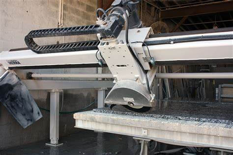
Bridge Miter saw are widely used for providing wide cutting widths. At present, the miter saw is widely used in the cutting occasions of various workpieces. The operator can optionally move the saw blade to any one of multiple positions or one of multiple modes to perform vertical cutting, bevel cutting, bevel cutting or compound miter cutting.
At present, it is cumbersome and not flexible to adjust the disc Angle of miter saw in the market.
The utility model aims at the disadvantage of cumbersome adjustment of disc Angle in the existing technology and provides an Angle positioning device applied in the miter saw.
In order to solve the above technical problems, the utility model is solved through the following technical solutions:
An application perspective in the miter saw positioning device, including the base and working plate, base including dial, dial with fixed positioning, positioning piece is equipped with multiple limit grooves, plate including the disc and turn the handle, turn the handle is fixed on the disc side, turn the handle on the radial disk, disk with the first cavity, turn the handle with the second chamber, the first chamber and a second cavity connected, between disc and dial with positioning spring leaf, positioning spring leaf end fixed on the first cavity in the body of the disk, locating on the other side of the leaf spring with CARDS, card and positioning on a chip of limit groove CARDS close connection, The second cavity inside the rotating handle is provided with a stilt, on which is a first position hole, and the side wall of the rotating handle is provided with a second position hole; The stilt is positioned in the rotating handle through the second positioning hole and the first positioning hole. One end of the stilt is under the positioning spring plate, and the other end of the stilt is provided with a raised button, which extends the upper end face of the rotating handle. The button is integrated with the stilt.
As a preference, the inner end of the positioning spring sheet is bolted to the rotating handle, and the positioning spring sheet includes the first bending plate, which is bent upward to form the second bending plate, the second bending plate is inclined downward to form the third bending plate, and the second bending plate and the third bending plate are pressed downward to form a clip.
As a preference, the stilt is a plastic injection-molded stilt, which comprises a first stilt and a second stilt. A sleeve is fixed between the first stilt and the second stilt. The upper end face of the first stilt is on the same horizontal surface with the upper end face of the second stilt.
Because of this practical new type USES the above technical scheme, the significant technical effect: the operator only needs to press a button, rocker positioning spring up, so as to make the location of the spring piece and locating piece out, people can have a rotating disk, disk rotation is convenient, and effort, to read for people with dial on the disk rotation Angle.


